









An energy meter calibration certificate tells you how far one identified meter read from a reference at stated test points, and how confident the laboratory is in each figure. To use it, match the meter and test points to your requirement, read every error together with its uncertainty, and then apply the decision rule your contract or regulation names.
Check Which Meter and Measurement the Certificate Covers
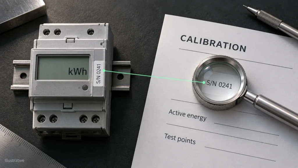
Start with identity, because a clean result for the wrong meter or the wrong quantity proves nothing. Match the model and serial number to the sample or installed meter, and confirm that the calibrated quantity is active energy; a voltage or power result does not, by itself, establish energy performance. The certificate should state:
- Issuing laboratory, certificate number and calibration date.
- Meter model, serial number and relevant configuration.
- Calibrated quantity, method and traceability.
- Test conditions, results and uncertainty statement.
- Any conformity statement, with its specification and decision rule.
If the contract asks for an accredited calibration, check that the laboratory’s scope of accreditation lists that measurement, range and service. Under ILAC P14, a scope states calibration and measurement capability by measurand, method, range and uncertainty, so an accreditation certificate on its own does not show which services a laboratory may report under accreditation.
Interpret the Error at Each Test Point
Relative energy error is the meter’s indication minus the reference value, divided by the reference value. OIML R 46 uses this definition and expresses the result as a percentage:
Error (%) = (meter indication − reference value) / reference value × 100
Read the Sign Correctly
Under this convention, a positive error means the meter recorded more energy than the reference, and a negative error means it recorded less. As an invented example, a meter that records 10.030 kWh against a 10.000 kWh reference has an error of (10.030 − 10.000) / 10.000 × 100 = +0.30%.
A column headed “correction” answers a different question: what to apply to an indication to obtain the result. ILAC G24, quoting the International Vocabulary of Metrology, notes that a calibration may be expressed as an additive or multiplicative correction of the indication. An additive correction normally carries the opposite sign to the error, so check how the certificate defines each column before you treat one as the other.

Keep the Conditions With the Result
An AC energy error belongs to the voltage, current, frequency and power factor at which it was measured, and to the energy-flow direction and phase arrangement where these apply. OIML R 46 specifies reference conditions (voltage, temperature, frequency, waveform) separately from load conditions (current and power factor) for its tests.
A small error at one current and unity power factor describes that point only. To judge light-load behaviour or performance at 0.5 inductive, read the result taken at that point. Compare the test points supplied with the points your specification names, rather than picking the smallest error on the certificate.
Read Uncertainty Alongside the Reported Error
The reported error is an estimate, and measurement uncertainty describes the spread of values that can reasonably be attributed to it. ILAC P14 expects the stated uncertainty to include contributions arising during calibration, including those from the customer’s meter, alongside the reference standard and method.
Interpret the Value and Its Units
Expanded uncertainty, written U, sets an interval around the result at a stated coverage probability. ILAC P14 asks accredited laboratories to report the result as y ± U and to state the coverage factor and coverage probability, so check the units and basis of U before you combine it with the error. In this invented entry, U is stated as a percentage of reference energy:
| Test conditions | Reported error | Expanded uncertainty | Coverage factor |
|---|---|---|---|
| 230 V, 5 A, 50 Hz, power factor 1.0 | +0.30% | 0.10% of reference energy | k = 2 |
Here U is 0.10 percentage points on the relative-error scale, so the interval runs from +0.20% to +0.40%. You do not take 0.10% of the printed +0.30% error. The meter’s accuracy class and any permitted error limits are separate requirements, and neither replaces the uncertainty attached to the result.

Check k and the Coverage Probability
The coverage factor k multiplies the combined standard uncertainty to give U. EA-4/02 states that k = 2 corresponds to a coverage probability of approximately 95% when a normal distribution can be assumed and the standard uncertainty is sufficiently reliable. If either condition fails, the laboratory needs a different k to reach the same probability. For the same standard uncertainty a larger k gives a wider interval, so compare figures from two laboratories only after checking that their coverage probabilities and units match.
Decide Whether the Result Meets Your Acceptance Requirement
Acceptance depends on the specification and on the decision rule, which states how measurement uncertainty is taken into account. ILAC G8 describes simple acceptance, where the acceptance limit equals the specification limit, and guarded rules, where a guard band narrows the acceptance interval. The same guide notes that under simple acceptance, a result sitting exactly on the limit has up to a 50% chance of being out of tolerance.
The invented example below uses specification limits of −1.00% and +1.00%, which are not YTL specifications. Its guarded rule accepts a result only when the whole e ± U interval sits inside those limits, which is the same as a guard band equal to U.
| Error e | Expanded uncertainty U | e ± U interval | Simple acceptance based on e | Acceptance under the stated guarded rule |
|---|---|---|---|---|
| +0.30% | 0.10 percentage points | +0.20% to +0.40% | Accepted | Accepted |
| +0.90% | 0.20 percentage points | +0.70% to +1.10% | Accepted | Not accepted |

In the second row the error sits inside the limits but the interval crosses +1.00%, so simple acceptance passes it and the guarded rule does not. Apply the rule your requirement names, including any rule a regulation prescribes. ILAC G8 expects the rule to be agreed before measurement, so if you need a pass/fail statement, agree the specification, decision rule and covered results when you order the calibration. A certificate without a pass/fail statement still gives you the evidence; you assess it against your agreed requirement.
Distinguish Calibration From MID and Factory Test Documents
A calibration certificate reports measurement results for one identified instrument. An EU type-examination certificate (Module B) under the Measuring Instruments Directive 2014/32/EU covers the technical design of an instrument type and is only one part of conformity assessment. The route is completed by a production module such as D or F, after which the manufacturer issues a declaration of conformity.
Keep these documents apart in the procurement file. A type-examination certificate does not replace a sample’s error and uncertainty results, and a calibration does not complete product conformity assessment. If the contract specifies an accredited calibration certificate, confirm that exact deliverable rather than accepting a factory test report or another differently scoped document, because the documents you need depend on the model, configuration, intended use and destination country.
Request Model-Specific Documentation From YTL
YTL’s three-phase DIN-rail meters come in direct-connected and CT/PT-operated versions, and the connection decides what a calibration request has to define. Both models below are covered by EU type-examination certificates under the Measuring Instruments Directive 2014/32/EU (Module B), issued by SGS Fimko Oy, Notified Body 0598.
| Model | EU type-examination certificate | Connection | Accuracy class (nameplate) | Define in the calibration request |
|---|---|---|---|---|
| DEM3A302 | 0598/MID/B/26/011 | Three-phase direct, 3P4W or 3P3W, Imax 100 A | IEC 62053-21 Class 0.5; EN 50470-3 Class C | Test currents, phase conditions and energy-flow direction |
| DEM3K302 | 0598/MID/B/26/010 | Three-phase CT/PT-operated, CT input 5(6) A | IEC 62053-22 Class 0.5S; EN 50470-3 Class C | Whether the evidence covers the meter alone or a defined chain, naming any external transformers |
Ask us for the full certificate and the declaration of conformity for your variant, and quote each accuracy class together with the standard it belongs to. YTL’s test centre is accredited by CNAS to ISO/IEC 17025:2017 (registration no. CNAS L12672) and supports meter development and production quality control. Accredited scope is confirmed activity by activity, so for work that needs an accredited result, ask which tests the scope covers before you order.
When you contact YTL, give the model, destination country, intended use and the document type you need. For a serial-number-specific calibration certificate, add the test points, decision rule and acceptance limits, and agree the document scope at the sample stage, before you confirm the order.
FAQs
Does an Energy Meter Calibration Certificate Expire?
Not in a fixed sense: the certificate records results on the calibration date and carries no universal validity period. ILAC G24 advises against fixed recalibration intervals unless a normative document specifies one, and lists factors such as the required uncertainty, drift, extent of use, environment, intermediate checks and legal requirements. Set the interval from those factors and the meter’s own calibration history.
What Do As-Found and As-Left Results Mean?
As-found results describe the meter before any adjustment, and as-left results describe it after the work. Request both before work starts if you need to judge earlier readings as well as the meter’s return to service. ILAC G24 names this check as one purpose of calibration: confirming whether the instrument changed in a way that casts doubt on results delivered since its previous calibration.
Is Calibration the Same as Adjustment?
No. Calibration establishes the relationship between reference values and indications, with their uncertainties, while adjustment changes the measuring system so that its indications match prescribed values. The International Vocabulary of Metrology keeps the two apart and notes that a system usually needs recalibrating after adjustment, so agree in advance whether adjustment is authorised and which results you need afterwards.
Sources
- OIML R 46-1/-2 Edition 2012 (E): Active electrical energy meters, Part 1 and Part 2, International Organization of Legal Metrology: definition of relative error of indication; separate reference and load conditions for tests.
- ILAC-P14:09/2020 ILAC Policy for Measurement Uncertainty in Calibration, ILAC: content of an accreditation scope; reporting y ± U with coverage factor and coverage probability; contributions to reported uncertainty.
- EA-4/02 M: 2022 Evaluation of the Uncertainty of Measurement in Calibration, European co-operation for Accreditation: k = 2 and approximately 95% coverage, and the conditions that apply.
- ILAC-G8:09/2019 Guidelines on Decision Rules and Statements of Conformity, ILAC: simple acceptance, guard bands and agreeing the decision rule before measurement.
- ILAC-G24:2022 / OIML D 10:2022 Guidelines for the Determination of Recalibration Intervals of Measuring Equipment, ILAC and OIML: recalibration intervals, purposes of calibration, and the quoted definitions of calibration and adjustment.
- JCGM 200:2012 International Vocabulary of Metrology (VIM), 3rd edition, Joint Committee for Guides in Metrology: terms for calibration, correction, adjustment and measurement uncertainty.
- Directive 2014/32/EU on the harmonisation of the laws of the Member States relating to the making available on the market of measuring instruments (recast), EUR-Lex: Module B type examination as one part of conformity assessment.
