
Locate the accountable energy point
Determine whether the project requires PCC, inverter AC output, battery DC path, PCS-side, load-feeder or DC-bus measurement.

YTL provides AC and DC energy meters for solar PV and energy storage systems, supporting grid connection, inverter monitoring, battery systems and energy management applications.
Determine whether the project requires PCC, inverter AC output, battery DC path, PCS-side, load-feeder or DC-bus measurement.
Review import, export, charge and discharge data together with CT polarity, phase sequence and the intended allocation rule before commissioning.
Confirm the controller, gateway or EMS, required registers, polling approach and project acceptance checks before choosing an interface by model.
Use these three decisions to create a clear product-selection brief. A verified meter is one part of the system; site wiring, sensors, controller logic and commissioning also affect the final result.
Confirm 3P3W or 3P4W, direct connection or CT/PT input, continuous current, cabinet space and whether the data supports monitoring, allocation or a regulated billing use.
Confirm DC voltage and current, shunt or sensor method, polarity, auxiliary supply, isolation requirements and the physical location within the cabinet.
Provide the inverter or PCS controller name, interface, register requirements, data interval, gateway topology and the acceptance test for the meter-to-platform data path.
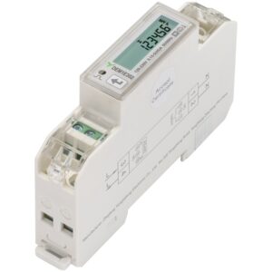
45 A Single-Phase DIN-Rail Energy Meter with RS485 and TOU
View Products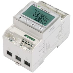
DEM3A302 100 A Three-Phase DIN-Rail Energy Meter with RS485 and TOU
View Products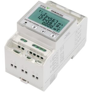
6 A Three-Phase CT-Operated DIN-Rail Energy Meter with RS485 and TOU
View Products
200–2400 A Single-Module Anti-Reverse-Flow Energy Meter with Rogowski Coil and WiFi/Bluetooth
View Products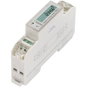
45 A Single-Phase DIN-Rail Energy Meter with SO Pulse Output
View Products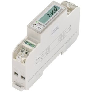
45 A Single-Phase DIN-Rail Energy Meter with RS485
View Products 45 A Single-Phase DIN-Rail Energy Meter with RS485 and TOU
View Products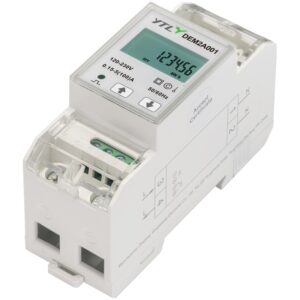
100 A Single-Phase DIN-Rail Energy Meter with SO Pulse Output
View Products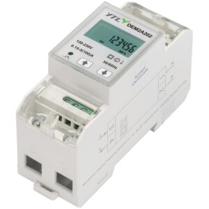
100 A Single-Phase DIN-Rail Energy Meter with RS485
View Products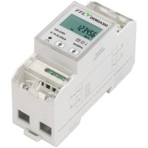
100 A Single-Phase DIN-Rail Energy Meter with RS485 and TOU
View Products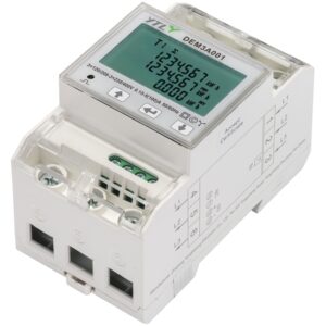
100 A Three-Phase DIN-Rail Energy Meter with SO Pulse Output
View Products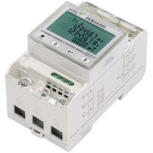
100 A Three-Phase DIN-Rail Energy Meter with RS485
View Products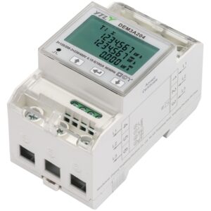
DEM3A204 100 A Three-Phase DIN-Rail Energy Meter with M-Bus
View Products DEM3A302 100 A Three-Phase DIN-Rail Energy Meter with RS485 and TOU
View Products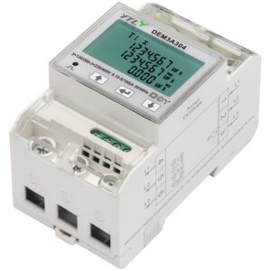
DEM3A304 100 A Three-Phase DIN-Rail Energy Meter with M-Bus and TOU
View Products
DEM3K001 6 A Three-Phase CT-Operated DIN-Rail Energy Meter with SO Pulse Output
View Products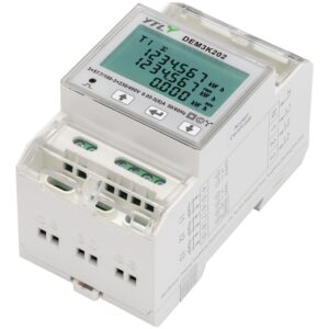
DEM3K202 6 A Three-Phase CT-Operated DIN-Rail Energy Meter with RS485
View Products 6 A Three-Phase CT-Operated DIN-Rail Energy Meter with RS485 and TOU
View Products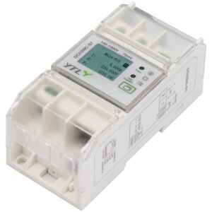
75 mV External-Shunt DC Energy Meter with RS485 and Ethernet
View Products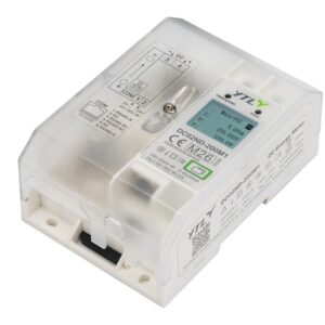
200 A Integrated-Shunt DC Energy Meter with RS485 and Ethernet
View Products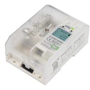
400 A Integrated-Shunt DC Energy Meter with RS485 and Ethernet
View Products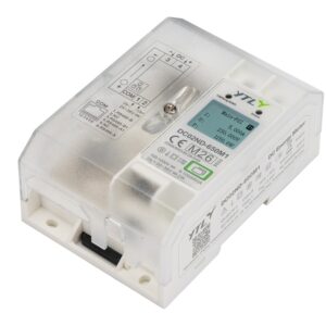
650 A Integrated-Shunt DC Energy Meter with RS485 and Ethernet
View Products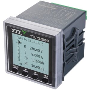
72 mm Panel-Mount Multifunction Power Meter with RS485
View Products 72 mm Panel-Mount Multifunction Power Meter with RS485 and DI/DO
View Products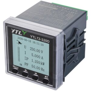
72 mm Panel-Mount Multifunction Power Meter with RS485, Y-Bus and DI/DO
View Products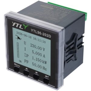
96 mm Panel-Mount Multifunction Power Meter with RS485 and Harmonic Analysis
View Products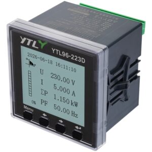
96 mm Panel-Mount Multifunction Power Meter with RS485, Y-Bus and Harmonic Analysis
View Products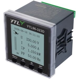
96 mm Panel-Mount Multifunction Power Meter with RS485, Y-Bus, Tariff and Harmonic Analysis
View Products
100 A Single-Phase DIN-Rail Energy Meter with Dual SO Pulse Output
View Products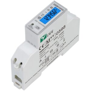
100 A Single-Phase DIN-Rail Energy Meter with RS485
View Products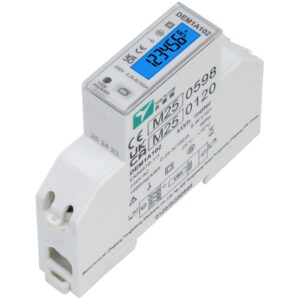
100 A Single-Phase DIN-Rail Energy Meter with RS485 and Multi-Tariff
View Products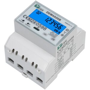
100 A Three-Phase DIN-Rail Energy Meter with RS485 and Dual SO Output
View Products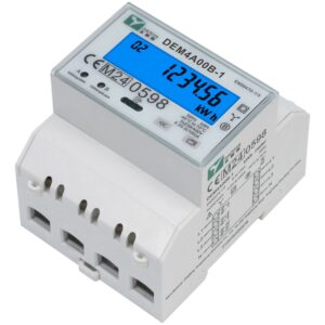
100 A Three-Phase DIN-Rail Energy Meter with RS485 (Bottom-to-Top Wiring)
View Products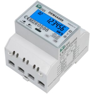
100 A Three-Phase DIN-Rail Energy Meter with IR and Dual SO Output
View Products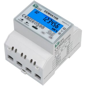
100 A Three-Phase DIN-Rail Energy Meter with RS485, Multi-Tariff and Dual SO Output
View Products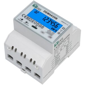
100 A Three-Phase DIN-Rail Energy Meter with RS485, SO Output and Signal Input
View Products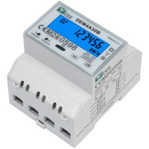
100 A Three-Phase DIN-Rail Energy Meter with RS485, Multi-Tariff, SO Output and Signal Input
View Products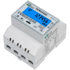
100 A Three-Phase DIN-Rail Energy Meter with M-Bus and Dual SO Output
View Products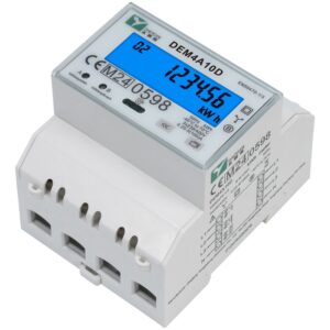
100 A Three-Phase DIN-Rail Energy Meter with M-Bus, Multi-Tariff and Dual SO Output
View Products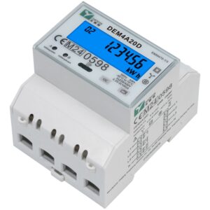
100 A Three-Phase DIN-Rail Energy Meter with M-Bus, SO Output and Signal Input
View Products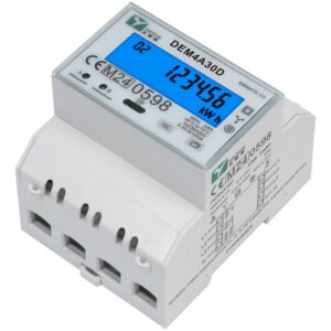
100 A Three-Phase DIN-Rail Energy Meter with M-Bus, Multi-Tariff, SO Output and Signal Input
View Products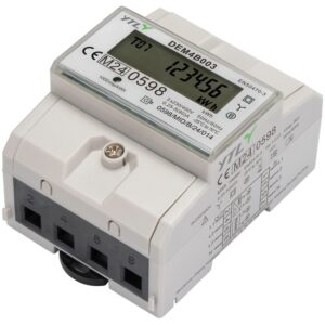
80 A Three-Phase DIN-Rail Energy Meter with RS485
View Products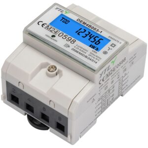
80 A Three-Phase DIN-Rail Energy Meter with RS485 and LCD Backlight
View Products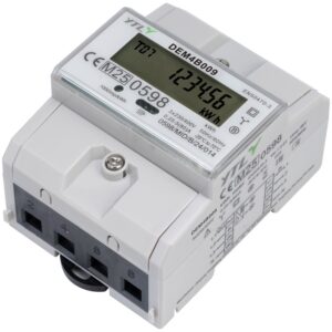
80 A Three-Phase DIN-Rail Energy Meter with Infrared Communication
View Products
80 A Three-Phase DIN-Rail Energy Meter with Infrared Communication and LCD Backlight
View Products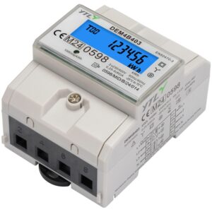
80 A Three-Phase DIN-Rail Energy Meter with RS485 and Power Outage Display
View Products
80 A Three-Phase DIN-Rail Energy Meter with RS485 and Power Outage Display
View Products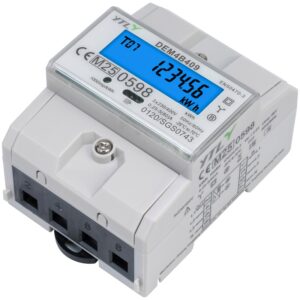
80 A Three-Phase DIN-Rail Energy Meter with Infrared Communication and Power Outage Display
View Products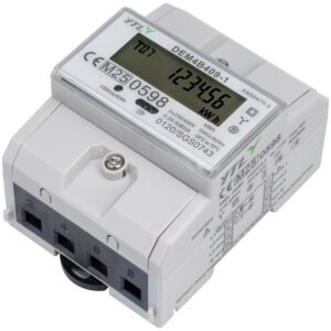
80 A Three-Phase DIN-Rail Energy Meter with Infrared Communication and Power Outage Display
View Products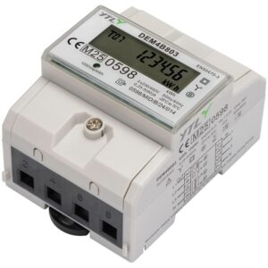
80 A Three-Phase DIN-Rail Energy Meter with RS485, RTC and Multi-Tariff
View Products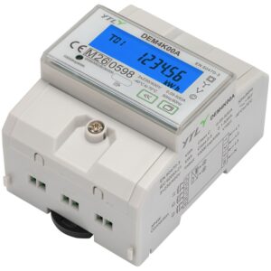
6 A Three-Phase CT-Operated DIN-Rail Energy Meter with Infrared Communication
View Products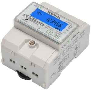
6 A Three-Phase CT-Operated DIN-Rail Energy Meter with Infrared Communication, RTC and Multi-Tariff
View Products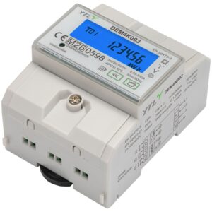
6 A Three-Phase CT-Operated DIN-Rail Energy Meter with RS485
View Products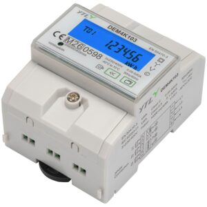
6 A Three-Phase CT-Operated DIN-Rail Energy Meter with RS485, RTC and Multi-Tariff
View Products
100 A Single-Module Anti-Reverse-Flow Energy Meter with CT and WiFi/Bluetooth
View Products 200–2400 A Single-Module Anti-Reverse-Flow Energy Meter with Rogowski Coil and WiFi/Bluetooth
View Products
200–2400 A Single-Module Anti-Reverse-Flow Energy Meter with Rogowski Coil and 4G
View Products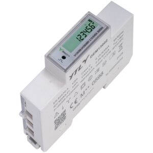
45 A Three-Phase Four-Wire DIN-Rail Energy Meter for EV Charging
View Products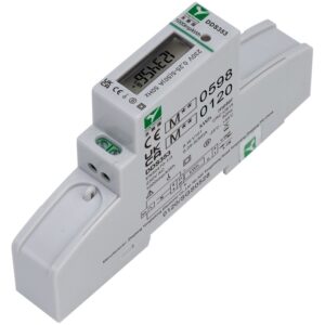
50 A Single-Phase DIN-Rail MID Sub-Billing Energy Meter
View Products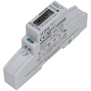
50 A Single-Phase DIN-Rail MID Sub-Billing Energy Meter
View Products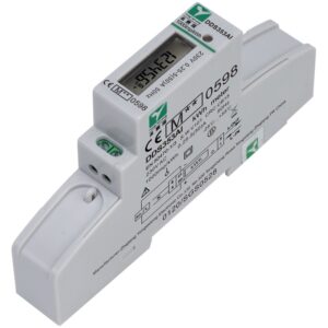
50 A Single-Phase DIN-Rail MID Sub-Billing Energy Meter
View Products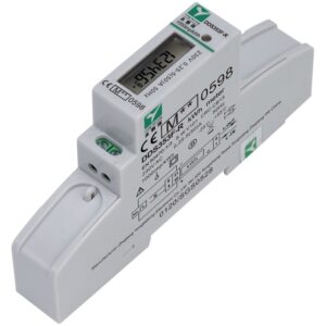
50 A Single-Phase DIN-Rail MID Sub-Billing Energy Meter
View Products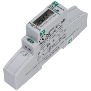
50 A Single-Phase DIN-Rail MID Sub-Billing Energy Meter
View Products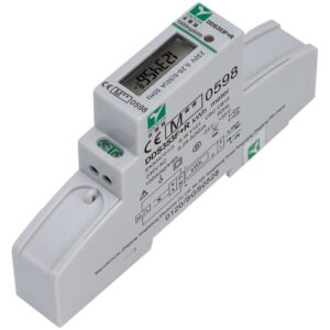
50 A Single-Phase DIN-Rail MID Sub-Billing Energy Meter
View Products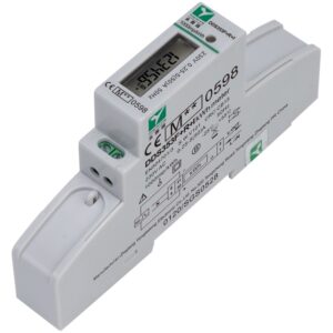
50 A Single-Phase DIN-Rail MID Sub-Billing Energy Meter
View Products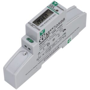
50 A Single-Phase DIN-Rail MID Sub-Billing Energy Meter
View Products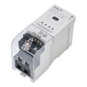
80 A Single-Phase DIN-Rail Prepayment Meter with G3 PLC
View Products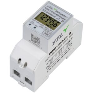
Single-Phase Prepaid Power Data Collector with 4G
View Products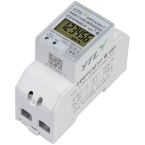
Single-Phase Prepaid Power Data Collector with WiFi
View Products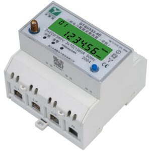
Three-Phase Prepaid Power Data Collector with 4G
View Products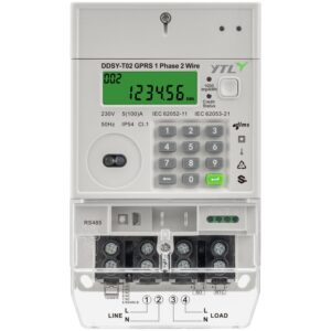
Single-Phase Two-Wire Wall-Mounted 4G Smart Prepayment Meter
View Products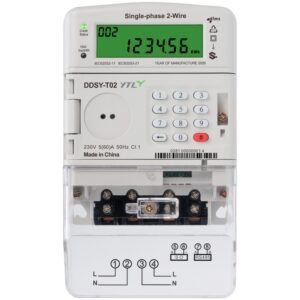
GPRS Single-Phase STS Wall-Mounted Prepayment Meter
View Products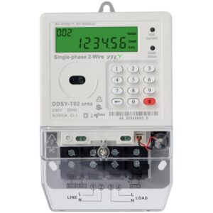
Single-Phase STS Prepayment Meter
View Products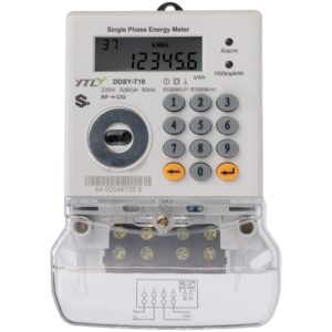
Single-Phase Prepayment Meter with WiFi and Bluetooth
View Products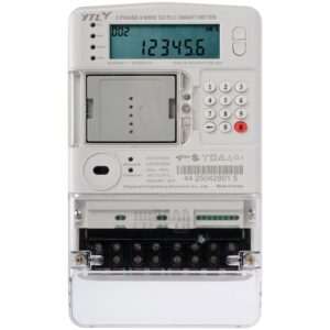
Three-Phase STS Wall-Mounted Prepayment Meter
View Products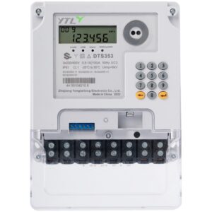
Three-Phase Prepayment Meter with WiFi and Bluetooth
View Products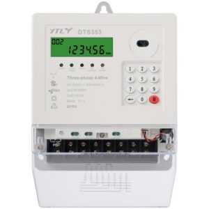
Three-Phase STS Prepayment Meter
View Products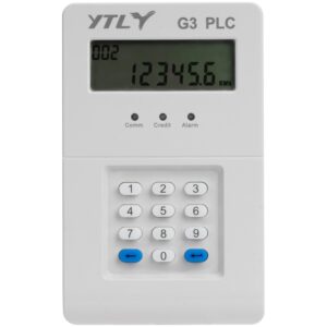
G3-PLC In-Home Display (IHD)
View Products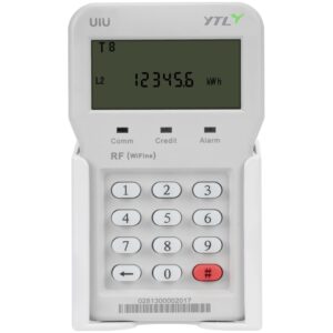
RF In-Home Display (CIU)
View Products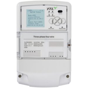
Smart Data Concentrator Unit (DCU) for AMI
View Products Smart Data Concentrator Unit (DCU) for AMI
View Products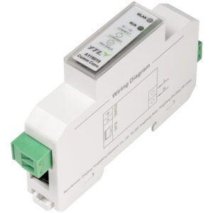
RS485 to Ethernet/WiFi Converter
View ProductsMark every measurement point on the single-line diagram: PCC, inverter output, battery path, load feeder or DC bus.
Do not use an AC meter route for DC-side measurement, or a DC route for an AC feeder.
Provide phase and wiring method, nominal voltage, maximum continuous current, and CT/PT or shunt details where applicable.
State whether import, export, charge, discharge or net-energy values are required and how the controller will use them.
Share the controller interface, register list, data interval, gateway topology and acceptance criteria.
Plan polarity, phase-sequence, communication-loss and on-site data comparison checks before project handover.
The correct measurement point depends on what the project needs to monitor or control. Common locations include the point of common coupling (PCC), inverter AC output, load feeder, battery charge/discharge path and DC bus. The single-line diagram should be reviewed first so the meter is placed at the correct accountability point and the project can determine whether AC-side or DC-side metering is required.
No. An energy meter alone cannot guarantee zero-export performance. The meter or sensor provides measurement data, but actual zero-export control depends on the complete control loop, including wiring and polarity, communication, inverter or EMS logic, controller response and site commissioning. The full system should be validated under the project’s operating and acceptance conditions.
DC-side meter selection should start with the DC voltage and maximum current, followed by the current-sensing method, installation and system requirements. Confirm whether the project uses an integrated shunt, external shunt or other sensor arrangement, and check polarity, auxiliary supply, isolation requirements, mounting space, communication interface and the intended measurement purpose. DC power rating alone is not sufficient to select the meter.
Energy meter integration with an EMS or PV/ESS controller depends on the exact meter interface, communication protocol, register map, required data points and system architecture. The gateway or controller route, polling interval and data-acceptance criteria should be defined before deployment. Compatibility should be verified for the selected meter and controller combination rather than assumed from the communication interface alone.
Tell us your requirements and our team will provide a professional solution and quotation within 24 hours.
 Optimized by Seraphinite Accelerator