









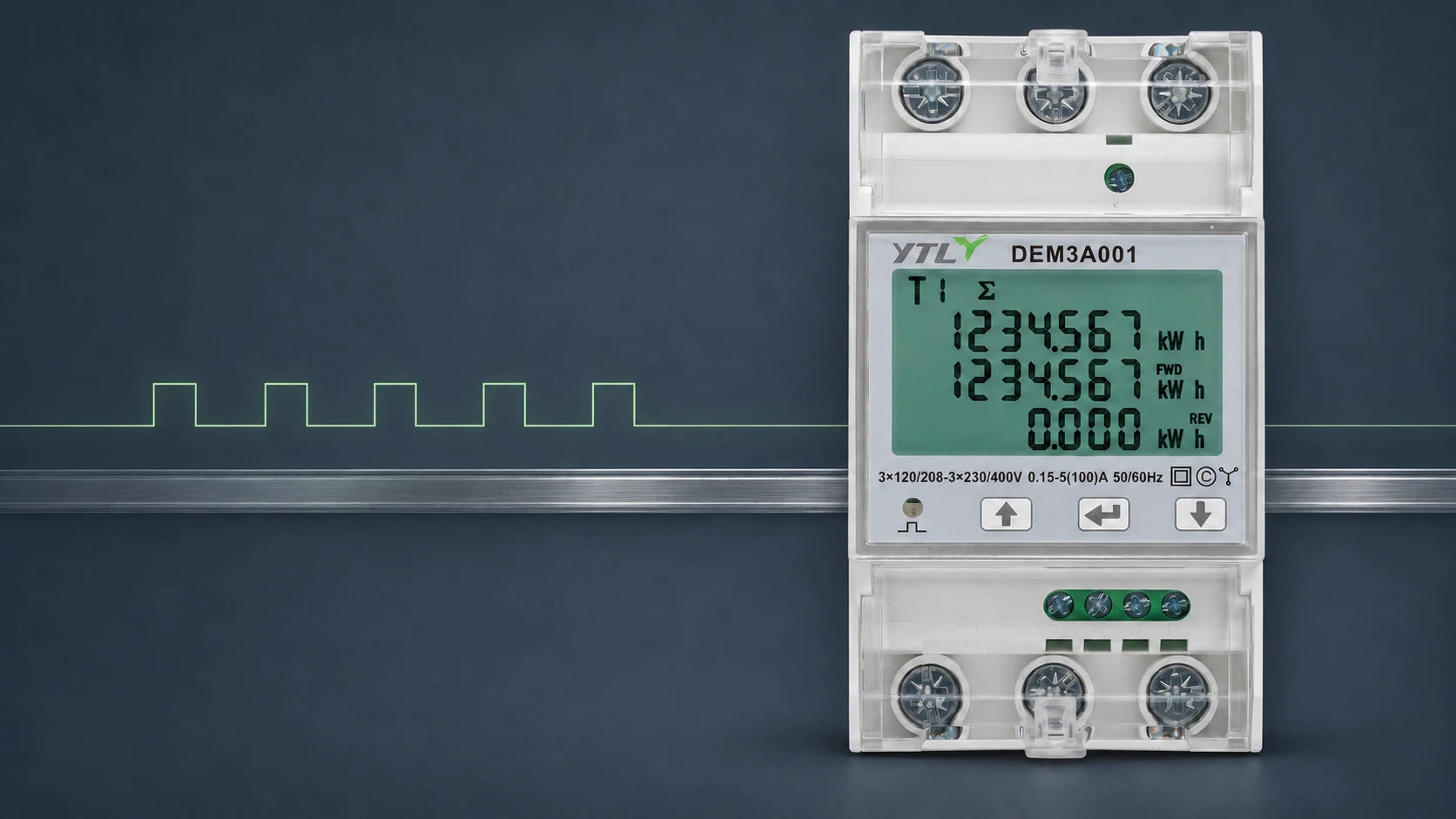
A DIN-rail kWh meter suits a data logger when the logger input accepts the meter’s electrical pulse signal and can count every pulse at the highest expected load. The logger must then convert counts into kWh with the right pulse value. Work from the exact meter variant and the logger’s input specification, not from the series name.
Confirm That You Have the Pulse-Output Model
Wired pulse counting needs an external pulse-output terminal. A flashing energy LED needs an optical pickup instead, and an RS485 port delivers register readings rather than pulses.
On YTL’s DEM1E, DEM2A, DEM3A and DEM3K DIN-rail energy meters, the model code fixes the interface. The 001 model has one SO pulse output and no RS485 port, while the 202 and 302 models use RS485 and have no SO output. The 001 models also have no tariff function, so a project that needs time-of-use registers as well as pulses has to settle that before the order.
Match the Electrical Output to the Logger Input
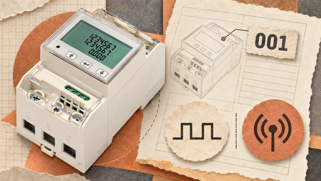
Logger inputs are usually configured for dry contacts, open-collector outputs or voltage pulses, each with its own wiring and excitation arrangement. Put the meter’s output specification next to the logger’s input specification and settle every row before you connect anything:

| Check | What to establish before connection |
|---|---|
| Signal type | The logger accepts the meter’s documented electrical output |
| Supply or excitation | Whether the input provides excitation or needs an external source |
| Voltage and current | The proposed circuit stays within both devices’ limits |
| Polarity and reference | The terminal polarity and reference arrangement agree |
| Isolation | The connection preserves the required isolation |
| Cable installation | Cable type, length and routing follow the equipment instructions |
| Interface label | If the specification calls for S0, the supply voltage range, maximum current and polarity of YTL’s “SO pulse output” meet the receiver’s requirements |
Check Pulse Timing at the Highest Expected Load
A logger can accept the electrical signal and still miss counts if pulses are too short or arrive too quickly. Check the input in the mode you will actually run, filtering included.

Compare Pulse Width and Input Filtering
Pulse width is the time the output stays active. Check the logger’s minimum recognised active and inactive times, including any debounce filter used to reject contact bounce. A debounce setting meant for mechanical contacts can cut the maximum counting rate sharply. Loggers often publish separate limits for each input mode, so take the figures for the receiver and configuration you’ve actually chosen rather than the headline rate on the datasheet.
Calculate the Required Counting Rate
For an output specified in pulses per kWh, the average pulse frequency at a steady active power is:
Pulse frequency (Hz) = Power (kW) × Pulse constant (pulses/kWh) ÷ 3,600
As an invented example, 1,000 pulses/kWh at 36 kW gives 36 × 1,000 ÷ 3,600 = 10 pulses per second. A receiver rated for a maximum counting frequency of 5 Hz cannot reliably capture a 10 Hz pulse train. The number of missed pulses depends on the input circuit, filtering and pulse timing, so the recorded energy cannot be trusted under those conditions.
Calculate with the total active power the output represents, which on a CT-operated meter may be the secondary-side power. Keep an operating margin and check that the meter’s pulse duration and spacing support the rate too. If the pairing fails, choose a faster receiver or a documented alternative pulse setting where the meter supports one.
Set the Pulse Value and Energy Quantity Correctly
| Documented setting | Calculation |
|---|---|
| Pulses per kWh | Energy (kWh) = Pulse count ÷ Pulses per kWh |
| Wh per pulse | Energy (kWh) = Pulse count × Wh per pulse ÷ 1,000 |
At 1,000 pulses/kWh each pulse represents 1 Wh, so 2,500 pulses represent 2.5 kWh. Enter 1,000 into a field labelled “Wh per pulse” and the logger reports 2,500 kWh for the same count. Use the value documented for the external output, since a pulse constant printed beside the front-panel LED does not by itself establish the terminal output’s pulse value.
Convert Counts Into kWh
At 1,000 pulses/kWh each pulse represents 1 Wh, so 2,500 pulses represent 2.5 kWh. Enter 1,000 into a field labelled “Wh per pulse” and the logger reports 2,500 kWh for the same count. Use the value documented for the external output, since a pulse constant printed beside the front-panel LED does not by itself establish the terminal output’s pulse value.
Confirm Import, Export and Transformer Scaling
Identify which energy quantity drives the output. If you need separate import and export totals, confirm how the meter and the receiving channels provide each one. Several accumulation modes on the meter do not mean they reach the logger on separate channels. In a current-transformer (CT) installation, establish whether the pulse value already represents primary energy or needs the CT and voltage-transformer (PT) ratios applied in the logger. Record the decision at commissioning so nobody applies the ratios twice.
Verify the Recorded Energy Before Handover
Compare increases over the same period, not absolute totals, which differ whenever the counters started at different values. A good result verifies acquisition, not the meter’s calibration. Agree the acceptance criteria first, then:

- Record starting meter readings and pulse counts against a common time reference.
- Run the test long enough for pulse increments and display resolution to give a useful comparison, then record both again.
- Convert the count difference into kWh and compare it with the meter’s increase for the same energy quantity.
- Repeat at representative loads, including the highest practical test load, and note any gap to the design maximum.
- Test the agreed restart procedure, including count retention and how periods without counting are identified.
Select a YTL Meter for the Circuit and Receiver
Each 001 model provides one SO pulse output, with different current ratings and connection arrangements. YTL’s published product information lists meter pulse constants of 1,000 imp/kWh for DEM1E001, DEM2A001 and DEM3A001, and 10,000 imp/kWh for DEM3K001. These published constants must not be assumed to be the external SO terminal’s pulse rate without confirmation from the model-specific output specification.
| Circuit requirement | YTL pulse-output model | Rail width | Pulse constant in the manual |
|---|---|---|---|
| Single-phase direct, up to 45 A | DEM1E001 | 18 mm | 1,000 imp/kWh |
| Single-phase direct, up to 100 A | DEM2A001 | 36 mm | 1,000 imp/kWh |
| Three-phase direct, up to 100 A | DEM3A001 | 54 mm | 1,000 imp/kWh |
| Three-phase CT/PT-operated, CT input up to 6 A | DEM3K001 | 54 mm | 10,000 imp/kWh |
If the receiver reads Modbus RTU instead, order the RS485 version of the same series, for example the DEM3A302 on a three-phase direct circuit. Write the full model code on the purchase specification.
The manuals don’t confirm the SO output’s pulse value, pulse width or electrical ratings, so ask YTL for them together with the wiring document. Include these details in the request:
- Logger model and its input specification.
- Circuit phase, voltage, current and connection method.
- For the DEM3K001, the CT and PT ratios, so YTL can confirm whether pulses represent primary or secondary energy.
- Energy quantity to record and reporting interval.
- Destination country and order quantity.
FAQ
Can I Use the Meter’s Flashing LED Instead of Its Pulse Terminals?
Yes, with a compatible optical pickup and recorder. OIML R 46 sets the radiated test-output signal of the meters it covers between 550 nm and 1,000 nm, and the YTL DEM series manuals list a red pulse LED. You still need to confirm the LED’s pulse value and the pickup’s mounting arrangement on the actual meter.
Why Does a Pulse-Based Power Reading Update Slowly at Low Load?
The interval between pulses grows as power falls: at 1,000 pulses/kWh and a steady 100 W, the average interval is 3,600 ÷ (0.1 × 1,000) = 36 seconds. A receiver estimating power from the time between pulses has to wait for the next one, so if you need faster power readings, specify that before choosing pulse acquisition.
Can One Pulse Input Record Several Meters Separately?
No. A combined count cannot show each meter’s contribution, so give every meter its own counting channel, confirm the logger’s channel capacity and label each total with a clear meter identifier.
Source
- OIML R 46-1/-2 Edition 2012 (E), Active electrical energy meters, Part 1: Metrological and technical requirements, Part 2: Metrological controls and performance tests, International Organization of Legal Metrology: wavelength range for the radiated test-output signal (section 3.7.2).
