









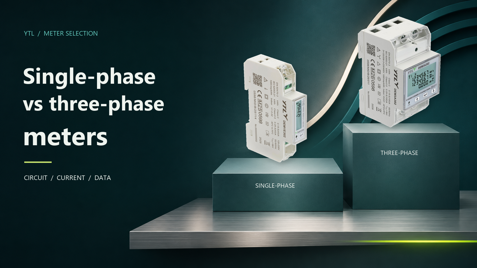
A single-phase meter measures a single-phase circuit; a three-phase meter measures a three-phase circuit. Select a model whose documented wiring modes, voltage and current inputs match the metering point. A building’s three-phase incoming supply does not determine the meter needed for every tenant or equipment branch.
What Is the Difference Between Single-Phase and Three-Phase Meters?
Compare the phase and wiring arrangement first, then the current rating at each input. Accuracy class, measured quantities and communication options vary by model, so take those from the individual datasheet.
| Comparison point | Single-phase meter | Three-phase meter |
|---|---|---|
| Circuit measured | A single-phase circuit | A three-phase circuit |
| Wiring arrangement | 1P2W: one phase conductor and a neutral | 3P3W (three-phase, three-wire) or 3P4W (three-phase, four-wire), depending on the model |
| Example: a 100 A direct-connected meter | 100 A maximum at the single-phase current input | 100 A maximum at each phase-current input, not a combined 100 A across all phases |
Match the Meter to the Circuit
Start with the distribution drawing and identify the conductors supplying the load. The metering point determines which electricity is included in the record, so fix that boundary before choosing a product.
Single-Phase Branches Within a Three-Phase Building
A commercial building often distributes its three-phase supply across many single-phase branches, so an individual office, lighting circuit or equipment supply may need single-phase measurement even though the main incomer is three-phase. For tenant metering, identify every supply serving the premises. If supplies come from different boards, include each one in the metering plan and define how their records will be combined.
Three-Phase Loads and Distribution Feeders
Use three-phase measurement where the metering point supplies all three phases, such as a distribution feeder or a dedicated three-phase equipment circuit. Check the 3P3W or 3P4W arrangement, nominal voltage and current connection against the model’s documentation, because all three must match the installation. A meter on a shared feeder records the total for every load behind it, so it cannot split that total between tenants supplied from the same feeder.

Choose Direct Connection or CT Metering
Direct-connected meters and meters using current transformers (CTs) apply their current ratings to different parts of the measurement system, so settle the current connection together with the phase and wiring arrangement.
| Selection factor | Direct-connected meter | CT-operated meter |
|---|---|---|
| Current measurement | Load current passes through the meter’s current terminals | External CTs supply a reduced secondary current to the meter |
| Meaning of the current rating | Applies to the load current through each rated meter input | Applies to the CT secondary current entering the meter, not the feeder’s load current |
| What must match | Circuit current, conductor size, terminal capacity and installation conditions | CT primary rating, secondary rating and ratio, together with the meter input and installation conditions |
The DEM3K302 manual, for example, specifies a 5 A basic and 6 A maximum input on the CT secondary side. Select the CT primary rating for the feeder and match its secondary output to the meter, since the 6 A limit says nothing about the feeder’s load capacity. When you compare direct and CT arrangements, count the meter, any CTs, cabinet space, wiring and commissioning in the total installed cost.

Compare YTL’s Standard DIN-Rail Options
YTL’s standard DIN-rail models cover direct-connected single-phase and three-phase circuits, plus three-phase CT inputs. Narrow the choice by current rating and cabinet space:
| YTL model | Measurement arrangement | Meter current input | Module width |
|---|---|---|---|
| DEM1E302 | Single-phase, direct-connected | 45 A maximum | 18 mm |
| DEM2A302 | Single-phase, direct-connected | 100 A maximum | 36 mm |
| DEM3A302 | Three-phase, direct-connected | 100 A maximum per phase | 54 mm |
| DEM3K302 | Three-phase, external CT input | 5 A basic, 6 A maximum secondary current | 54 mm |
All four 302 models have an LCD, RS485 Modbus RTU (Remote Terminal Unit) communication and time-of-use (TOU) energy recording, with four tariffs and eight time periods by default. In the cabinet layout, leave room for connected conductors, terminal access and any external CTs as well as the module width. Follow the exact model’s enclosure and installation instructions when approving the assembly.

Specify the Data and Billing Requirements
An electrically suitable meter still has to deliver the right information. Decide what will be read, where the records will go and whether they will support monitoring, internal allocation or customer billing.
Readings and System Integration
For manual collection, define the display registers and reading interval. For remote collection, specify the gateway, building management system (BMS) or other receiving system, then request the register map for the exact meter model and firmware. Register maps are manufacturer-specific, so the receiving system needs the matching addresses and data definitions. During sample acceptance, compare the same energy register on the meter and in the receiving system, checking the unit, scaling, energy direction and reading time.

Monitoring and Billing Approval
Identify the destination country and intended use before approving a meter for billing. For EU projects, check the Measuring Instruments Directive (MID) documentation for the exact model alongside national requirements, since Member States may prescribe instruments for particular measuring tasks. In Great Britain, the Office for Product Safety and Standards (OPSS) states that electricity meters with only Module B type approval are not approved for primary (supplier to consumer) or secondary (landlord to tenant) billing. Request the complete conformity documentation for the configuration you are buying.
Build Your Meter Specification With YTL
Give each metering point its own schedule entry so different circuit ratings and data requirements stay distinct. Include:
- The metering point, phase count, wiring system and voltage.
- Maximum circuit current, plus CT ratio and secondary rating where relevant.
- Required energy registers, communication protocol and receiving system.
- Available cabinet space, destination country and monitoring or billing purpose.
- Sample quantity, expected order quantity and project timing.
With that schedule, you can request a standard-model quotation with the matching datasheet, wiring diagram and communication documents, then use the agreed specification for sample approval and the production order.
FAQ
Can a Three-Phase Meter Be Used on a Single-Phase Circuit?
Yes, where the manufacturer documents a single-phase mode. The DEM3A series manual (V5.0, July 2026) lists 1P2W alongside 3P3W and 3P4W. Obtain the connection instructions for that configuration, and check during commissioning that the configured measurement mode matches the physical wiring, especially when an existing installation is reused. For billing, also confirm that the conformity documentation covers that use, because a listed wiring mode alone does not establish billing approval.
Will a Three-Phase Meter Increase the Available Power?
No. A meter measures electricity, and changing it does not upgrade the supply, cables or protection. A supply upgrade is a separate electrical project: UK Power Networks recommends asking a qualified electrician to assess the equipment you will run and how much power it needs.
Can Single-Phase and Three-Phase Meters Share a Modbus Network?
Yes, if they are compatible RS485 Modbus RTU devices on a correctly designed network. The Modbus serial-line specification requires a unique address for each device and matching serial settings, and each model’s register definitions must be configured in the receiving system. Phase count does not decide network compatibility; the interface, protocol and configuration do.
Source
- MIR approved gas and electricity meters, Office for Product Safety and Standards: Great Britain’s position that Module B alone does not approve a meter for primary or secondary billing.
- Directive 2014/32/EU on the harmonisation of the laws of the Member States relating to the making available on the market of measuring instruments (recast), EUR-Lex: the EU MID framework and Member States’ right to prescribe instruments under Article 3.
- MODBUS over Serial Line Specification and Implementation Guide V1.02, Modbus Organization: unique device addresses (section 2.1) and serial transmission modes (section 2.5).
- MODBUS Application Protocol Specification V1.1b3, Modbus Organization: vendor-specific mapping of the data model (sections 4.3 and 4.4).
- What’s the difference between a single phase and three phase electricity supply?, UK Power Networks: the electrician’s assessment of equipment and power demand.
