










A split-core current transformer (CT) has a magnetic core that opens on a hinge, so it can be clamped around a conductor that is already connected. That makes it the usual choice for adding metering to an existing distribution board, where threading a solid-core CT would mean disconnecting a cable or busbar.
The core joint introduces an additional factor that can affect ratio accuracy and phase displacement, particularly if the mating surfaces are not clean or fully closed. Actual accuracy depends on the CT’s design, accuracy class and operating conditions, while phase displacement can have a greater effect on active-energy measurement at low power factor.
How Does a Split-Core Current Transformer Work?
The conductor passes through the CT window and acts as a one-turn primary winding. Its alternating current sets up a magnetic flux in the core. That flux induces a smaller secondary current in the winding on the core, scaled by the turns ratio: a 200:5 A CT delivers 5 A when 200 A flows in the conductor. Some split-core CTs pass this current through an internal resistor and output a low voltage instead.
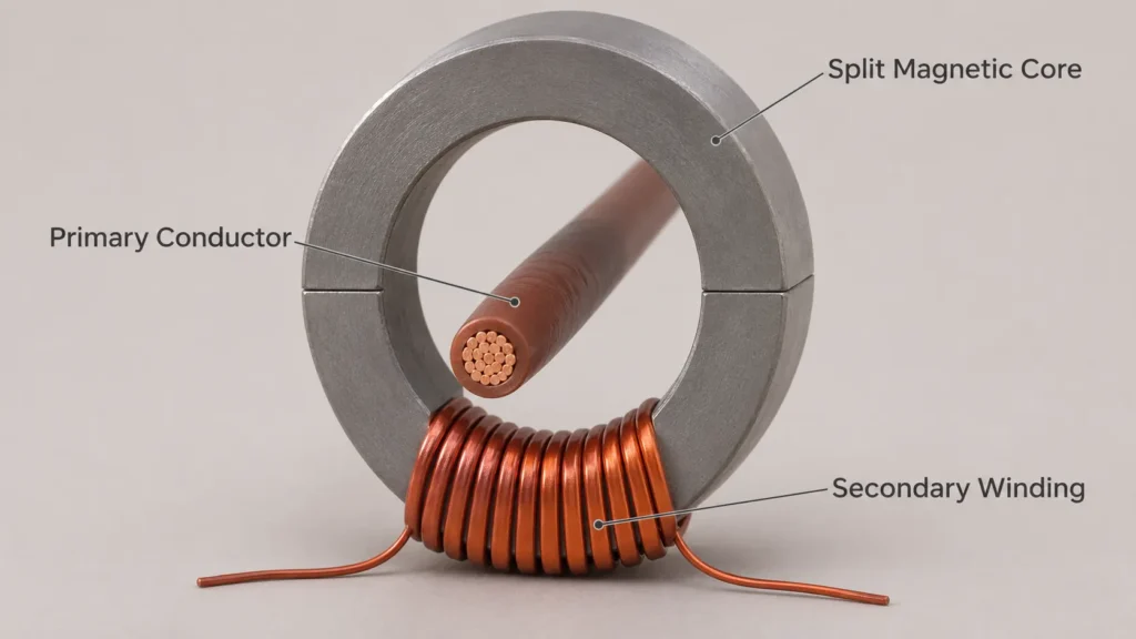
The core joint is an important feature of a split-core CT. Any effective air gap at the mating surfaces can increase magnetic reluctance and influence ratio accuracy and phase displacement. The magnitude and direction of these errors depend on the CT design and operating conditions. Dirt, trapped insulation or an incompletely closed latch can further affect the magnetic path and measurement performance.
How Do Split-Core and Solid-Core CTs Compare?
Solid-core and split-core CTs differ mainly in their mechanical construction and installation method. Their actual measurement accuracy depends on the selected design, accuracy class and operating conditions.
| Feature | Solid-core CT | Split-core CT |
|---|---|---|
| Installation | Conductor is disconnected and threaded through the window | Clamps around the existing conductor |
| Core | Continuous ring with no air gap | Two halves with a joint and a small air gap |
| Accuracy | Depends on the specified accuracy class, burden, current range and design | Depends on the same factors, with additional attention to core-joint condition and closure |
| Housing | Compact for its window size | Larger outside for the same window, because of the hinge and latch |
| Typical use | New switchgear and factory-built panels | Retrofit sub-metering in existing installations |

Phase displacement deserves the closer look. A meter calculates active energy from the angle between voltage and current, so a CT phase error of δ changes the kWh reading by roughly δ × tan φ. At power factor 0.5 (φ = 60°, tan φ ≈ 1.73), a 1° phase error (0.0175 rad) would shift the reading by about 3 %. At power factor 1 the same error is negligible. For lightly loaded motors and other low power factor loads, compare the phase displacement on the datasheet as well as the accuracy class.
Where no rigid core will fit at all, such as around a large busbar stack, the usual alternative is a flexible Rogowski coil. A Rogowski coil needs an integrator or a meter designed for its output.
Where Do Split-Core CTs Fit in Energy Metering?
Split-core CTs fit any metering point added after the board was built. The most common case is retrofit commercial and industrial sub-metering: adding meters to tenant feeders, chillers, lighting or departmental circuits in an occupied building, where reworking the cabling is hard to arrange. Compact split-core CTs also make it practical to monitor many outgoing circuits in one board without rewiring them.

The second case is export limitation in PV and battery systems. Where the grid connection allows zero or limited export, a meter at the connection point measures power and its direction. The inverter or energy management system then adjusts its output from that data. A split-core CT allows the measuring point to be added without disconnecting the primary conductor, although the installation must still follow the applicable electrical isolation and safety procedures.
Which Output Signal Matches Your Energy Meter?
Match the CT output to the meter input first. A split-core CT delivers either a current, usually 5 A or 1 A at rated primary current, or a low voltage, commonly 333 mV, and the two are not interchangeable:
| Point to check | 5 A or 1 A current output | 333 mV voltage output |
|---|---|---|
| Meter input | Current input, for example 5(6) A | Millivolt input of the same rating |
| Burden | External: the meter input plus the cable loop | Internal resistor inside the CT |
| Secondary wiring | Sized for current, typically 2.5 mm² or larger, through a shorting terminal block | Light twisted pair, shielded near busbars |
| Secondary opened while the primary carries current | Hazardous: the voltage can rise to thousands of volts | No hazardous voltage from the CT |
| Wrong pairing | Can damage a millivolt input | A 5 A input reads close to zero |

On current-output CTs, check the burden. The rated burden in VA is the load the secondary can drive while staying within its accuracy class, and it has to cover the meter input and the cable in both directions. A 15 m run of 2.5 mm² copper means 30 m of conductor, about 0.21 Ω (0.0175 Ω·mm²/m × 30 m ÷ 2.5 mm²). At 5 A that loop alone takes 5² × 0.21 ≈ 5.3 VA, more than a 2.5 VA CT can drive on its own. Shorten the run, use a larger cable or choose a higher burden rating; a 1 A secondary cuts the loss on the same loop by a factor of 25.
What Should You Check Before Selecting a Split-Core CT?
Check these points on the datasheet and on site before you order:
- Measure the conductor over its insulation and choose a window the core halves can close around without force.
- Measure the housing against neighbouring cables, busbars and the enclosure wall.
- Size the rated primary current to the load the circuit actually carries, not only to the breaker rating.
- Confirm that the output matches the meter input and that the burden covers the meter and the cable.
- Compare the accuracy class and phase displacement at the lowest current the circuit will run at.
- Fit each CT with its P1 (K) side towards the supply and on the same phase as the matching voltage input of the meter.
- Close the latch until it clicks and check that nothing is trapped between the core faces.

Point 3 is where oversizing creeps in. A 400 A breaker feeding a load that usually draws 50 A would leave a 400 A CT working at 12.5 % of its rating most of the time. IEC 61869-2 sets the limits for Class 0.5 and Class 1 from 5 % to 120 % of rated current, with larger errors allowed towards the bottom of that range. A CT rated nearer the real load therefore reads it more accurately. Point 6 matters because a CT fitted the wrong way round inverts its signal, and the meter records that phase as export instead of import.
Matching Our Meters to Split-Core CTs
We make DIN-rail meters for both set-ups. For conventional 5 A CTs, our DEM3K302 three-phase CT-operated meter has a 5(6) A CT input and accepts CT ratios up to 2000:1. A split-core CT with a 5 A secondary connects to it directly.

For PV export limitation, our meters for zero-export control supply power and direction data to the inverter or energy management system, which performs the export control. The M60315, for example, supports external split-core CT sampling up to 100 A and specifies a communication data refresh time of ≤50 ms.
To have us check the CT and meter pairing, send us the circuit current and the CT ratio or output you plan to use. Add the length of the cable run to the meter and the system that will read it.
FAQ
Can a Split-Core CT Be Installed on Live Cables?
A split-core CT can be fitted around an existing conductor without disconnecting the primary circuit, but this does not automatically make live installation safe or permissible. De-energise and verify the installation is safe whenever practicable. Work on or near energised equipment should only be considered where justified and permitted by the applicable regulations, site safety procedures and CT manufacturer’s instructions. It must be assessed and performed by qualified electrical personnel using the required protective measures. An insulated cable does not, by itself, remove the hazards of working inside an energised distribution board.
Can Split-Core CTs Be Used for MID Billing?
Not on their own. The Measuring Instruments Directive (MID) covers the energy meter, not the instrument transformers used with it, so a split-core CT carries no MID approval. For tenant billing with a CT-operated meter, check the national rules in the country of use, which can set separate requirements for the transformers.
Source
- IEC 61869-2:2012 Instrument transformers – Part 2: Additional requirements for current transformers, IEC, Edition 1.0: accuracy classes, ratio error and phase displacement limits for inductive CTs.
- Directive 2014/32/EU on the harmonisation of the laws of the Member States relating to the making available on the market of measuring instruments (recast), EUR-Lex: Annex V (MI-003) covers electricity meters but not instrument transformers.
