
Fit the Actual Cabinet
Review rail or panel position, available width and depth, terminal orientation, conductor bending, door clearance, ventilation, labeling and future maintenance access.

YTL supplies DIN-rail energy meters, panel-mounted power meters, current-sensing options and communication-enabled metering products for electrical panels and distribution cabinets. Model selection should consider the actual circuit, mounting space, terminal access, conductor route, sensing method, required data and project documentation.
Review rail or panel position, available width and depth, terminal orientation, conductor bending, door clearance, ventilation, labeling and future maintenance access.
Confirm AC or DC, phase, voltage, maximum current, direct or CT/PT connection, shunt or sensor route, transformer ratio and wiring reference.
Define the local-display requirement, device addressing, model-specific communication interface, gateway or controller position, required data points and commissioning access.
Give the project team a panel layout and a single-line diagram. These two documents expose most selection risks before a model is shortlisted.
Check rail width, available modules, terminal direction, conductor size, direct or transformer input and service access.
Check cutout dimensions, panel depth, display visibility, CT/PT inputs, auxiliary supply and the required power or energy data.
For dense or high-current cabinets, confirm conductor geometry, sensing method, range, mounting arrangement, data interface and isolation requirements.
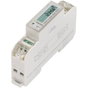
45 A Single-Phase DIN-Rail Energy Meter with SO Pulse Output
View Products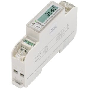
45 A Single-Phase DIN-Rail Energy Meter with RS485
View Products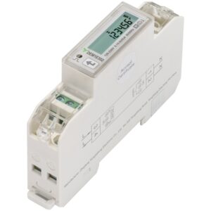
45 A Single-Phase DIN-Rail Energy Meter with RS485 and TOU
View Products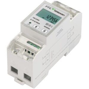
100 A Single-Phase DIN-Rail Energy Meter with SO Pulse Output
View Products 45 A Single-Phase DIN-Rail Energy Meter with SO Pulse Output
View Products 45 A Single-Phase DIN-Rail Energy Meter with RS485
View Products 45 A Single-Phase DIN-Rail Energy Meter with RS485 and TOU
View Products 100 A Single-Phase DIN-Rail Energy Meter with SO Pulse Output
View Products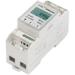
100 A Single-Phase DIN-Rail Energy Meter with RS485
View ProductsProvide the panel layout, rail schedule, cutout if applicable, door clearance, depth, ventilation or temperature conditions and maintenance-access limits.
Provide circuit location, AC or DC, phase, wiring method, voltage, maximum current and CT/PT, shunt or sensor details.
Confirm product dimensions, DIN modules or panel cutout, terminal access, conductor bending radius, label position, auxiliary supply and maintenance reach.
State the available auxiliary power and earthing or isolation constraints where the selected configuration requires them.
Identify local display, controller, RS485 or other verified model-specific interface, gateway location and required data points.
Plan wiring checks, CT or sensor polarity, phase verification, communication testing, display or platform comparison and technical-document handover.
At minimum, provide the electrical single-line diagram and cabinet layout. For panel-mounted products, also provide the cutout and panel-depth requirements. These documents show the electrical input, mounting space, terminal access, conductor route and likely data path.
Use the verified circuit voltage, current, connection method, transformer details and installation constraints. The decision must be based on the real electrical circuit, not cabinet size.
No. Rail space is only one constraint. The electrical input, terminal direction, conductor size, auxiliary supply, sensing route, data interface and maintenance access must also be confirmed.
Verify approved drawings, device configuration, wiring labels, electrical reading plausibility, communications, data mapping and the documents needed for site installation and acceptance.
Tell us your requirements and our team will provide a professional solution and quotation within 24 hours.
 Optimized by Seraphinite Accelerator