










An electricity sub meter records the kilowatt-hours (kWh) used by one tenant, floor or equipment circuit downstream of the building’s main meter, which gives operators separate records for cost allocation and energy management. Choose it by the circuit’s phase, voltage and current first, then by the reading method, then by the documents its intended use calls for.
Define the Tenant, Area or Load Being Metered
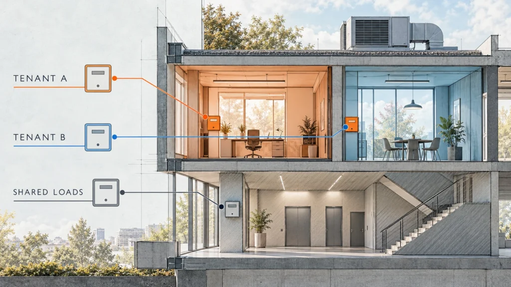
Start on the electrical drawing, not the product list, because each meter needs a clear measurement boundary. A meter on a tenant’s dedicated supply gives that unit’s consumption, while a floor meter covers every circuit fed through that point and supports tenant allocation directly only where the electrical and tenancy boundaries match. Shared services such as ventilation and common-area lighting need their own metering points if their cost is split separately, and timestamped readings let you compare consumption in occupied and unoccupied hours.
If one tenant draws power from several boards, decide now how those readings will be added together, and write down how shared loads will be allocated. It’s the tedious part of the job, and it’s the part that decides whether the meter schedule matches how the building is actually fed.
Choose the Electrical Type and Reading Method
Phase, current connection and reading method are separate choices, and one meter can be three-phase, CT-operated, DIN-rail mounted and remotely read at the same time. Specify each of them for every metering point.
Single-Phase or Three-Phase
Match the meter to the circuit it measures, not to the building’s incoming supply: a building on a three-phase supply often has single-phase tenant units and equipment circuits. In most European commercial buildings that means 230 V single-phase branches alongside 3×230/400 V three-phase circuits. Record the supply voltage and wiring arrangement with the phase count, and for three-phase circuits note whether the connection is three-wire or four-wire so the meter’s connection mode matches the system.
Direct-Connected or CT-Operated
A direct-connected meter carries the load current through its own terminals, so the circuit’s maximum current and conductor size must fit the meter’s current rating and terminal capacity.
A CT-operated meter measures the secondary current of external current transformers (CTs), which is the usual route for feeders above direct-meter ratings. Select the meter and CTs together, covering the primary-to-secondary ratio, secondary rating and installation arrangement. On a CT-operated meter the input rating refers to the CT secondary circuit, so specify the feeder’s maximum current and the CT ratio separately; the meter’s input rating isn’t the feeder’s limit.

Local Readings or Remote Collection
Local reading works where staff can reach the displays at the required interval, provided you decide who reads them and how each reading is tied to its meter and date. Remote collection connects the meters to a gateway or building management system (BMS) and suits frequent readings or meters spread across several boards. Specify the receiving system and the data it needs before you choose the communication version. Keep any requirement for payment before use separate, since that is a vending workflow in its own right and neither an LCD nor an RS485 port provides it.
For RS485 Modbus RTU meters, request the Modbus register map for the exact model and firmware before integration. The Modbus application protocol specification leaves the mapping between its data model and device memory to each vendor, so a shared protocol does not make register definitions interchangeable. Add a check of received values against the meter display to sample acceptance.

Check the Installation and Billing Requirements
Once the electrical type is clear, check that it fits the board and the purpose of the readings, because either can rule out a configuration that is electrically correct.
Cabinet Space and Installation Conditions
Allow space for the meter, its connections and later access. For CT-operated points, include the transformers and secondary wiring in the layout, and compare whole installed arrangements, gateway included, when you weigh cost against cabinet space.
These meters mount on a 35 mm DIN rail inside a meter enclosure, and enclosure protection differs between models, so confirm each model’s IP rating and the enclosure its manual calls for as part of the cabinet design. Have a qualified installer check conductor access, isolation and the model’s installation instructions.

Monitoring, Allocation or Tenant Billing
Say in the enquiry whether the readings support operational monitoring, internal cost allocation or tenant billing, because that decides which documents and acceptance checks apply.
For EU billing projects, ask for the selected configuration’s documents under the Measuring Instruments Directive 2014/32/EU, including the EU type-examination certificate and the declaration of conformity, and check national requirements in the destination country. In Great Britain the Measuring Instruments Regulations 2016 apply. Guidance from the Office for Product Safety and Standards (OPSS) states that a meter assessed only under Module B is not approved for supplier-to-consumer or landlord-to-tenant billing. For Saudi Arabia and the UAE, name the country in the enquiry so the required conformity documents can be checked.
Compare YTL’s Standard DIN-Rail Options
The four priority DIN-rail meters on our commercial and industrial sub-metering page share RS485 with Modbus RTU and DL/T 645-2007 and a backlit LCD. All four also offer time-of-use (TOU) metering with four tariffs and eight periods, timed by a real-time clock with battery backup. What separates them is the electrical connection, current rating and rail width.
| YTL model | Electrical connection and current | DIN-rail width | Selection cue |
|---|---|---|---|
| DEM1E302 | Single-phase direct, Imax 45 A | 18 mm (1 module) | Single-phase points where rail space is tight |
| DEM2A302 | Single-phase direct, Imax 100 A | 36 mm (2 modules) | Higher-current single-phase circuits up to 100 A |
| DEM3A302 | Three-phase direct, 3P4W or 3P3W, Imax 100 A | 54 mm (3 modules) | Three-phase metering without external CTs |
| DEM3K302 | Three-phase CT/PT-operated, CT input 5(6) A, CT ratio up to 2000:1 | 54 mm (3 modules) | Feeders beyond direct-meter ratings, with matched external CTs |
TOU records energy by tariff schedule, so the schedule and the registers you read must match the project’s reporting design. Each meter is covered by an EU type-examination certificate under the Measuring Instruments Directive 2014/32/EU (Module B), issued by SGS Fimko Oy, Notified Body 0598: DEM1E302 0598/MID/B/25/114, DEM2A302 0598/MID/B/25/105, DEM3A302 0598/MID/B/26/011 and DEM3K302 0598/MID/B/26/010. Ask us for the full certificate and the declaration of conformity for your variant.
Brand owners and distributors should build the purchasing specification around the selected model’s ratings, communication configuration and documents, and approve that exact configuration on samples before the volume order.
Specify Your Sub-Meter Order With YTL
Send a circuit schedule with one line per metering point, and we can match each line to a standard model. For every point, include:
- Application and destination country, stating monitoring, allocation or billing use.
- Phase, voltage, wiring arrangement and maximum circuit current.
- Direct or CT connection, with CT ratio and secondary rating where relevant.
- Quantity, free rail width and enclosure conditions.
- Local or remote reading, receiving system and required data interval.
Contact YTL with the schedule and expected quantity to request a quotation for standard models and the matching technical documents.
FAQ
Can Sub-Meters Be Added to an Existing Commercial Building?
Yes. Start with a survey of the distribution boards, circuit access and free rail space, and have a qualified installer settle the installation method and isolation arrangements. For remote collection, add the communication route and gateway location to the survey, and agree any shutdown with the building operator.
Should a Sub-Meter Be Reset When a Tenant Changes?
No. For a cumulative kWh register, take a dated handover reading as the new tenant’s baseline and calculate usage from the same continuous counter, recording the meter identity, register, reading and timestamp; do the same when the meter first enters service. If the model also has a separate resettable counter, follow its documented procedure.
Can Existing Sub-Meters Be Kept When the BMS Is Replaced?
Yes, if the new system can collect and interpret their data, directly or through a gateway. Give the integrator the meter model, firmware version, communication settings and register map, and test the required readings on one connection before extending the integration to the remaining meters.
Sources
- MODBUS Application Protocol Specification V1.1b3, Modbus Organization: mapping between the Modbus data model and the device application is vendor-specific.
- Measuring & weighing instruments in the EU, European Commission: scope of the Measuring Instruments Directive 2014/32/EU and its amendments.
- MIR approved gas and electricity meters, Office for Product Safety and Standards: GB approval routes and the billing status of Module B-only meters.
