









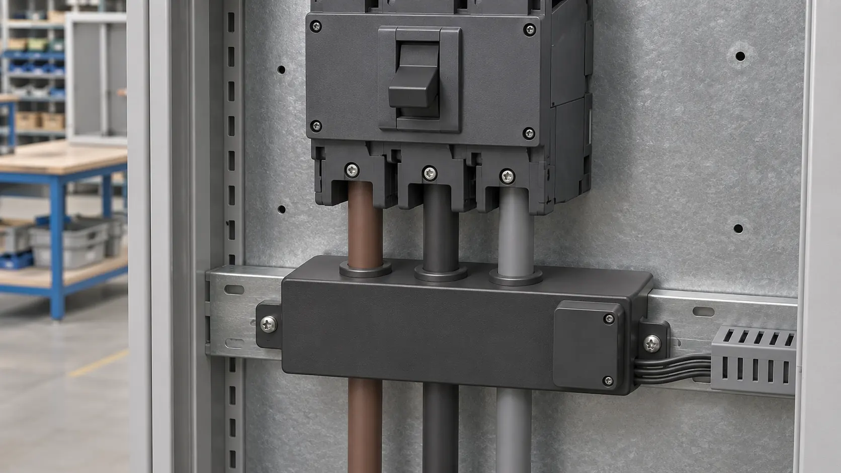
Choose a three-phase current transformer (CT) set by fit before anything else. The windows have to clear the insulated conductors, and the housings have to sit within the breaker’s pole pitch and the enclosure depth. Only then do the secondary and the meter come into it. A CT that is electrically right but physically wrong tends to show up on site, once the cables are already in place.
Three-Phase CT Types for Switchboards and Distribution Panels
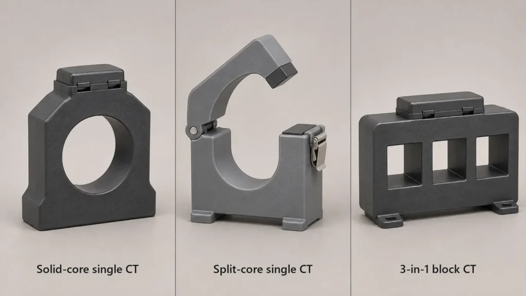
A three-phase CT set is described by two separate choices: how each core is built and how the three CTs are packaged. A 3-in-1 block is a packaging choice, so it can be either solid-core or split-core:
| Choice | Options | What it decides |
|---|---|---|
| Core construction | Solid-core or split-core | Whether the conductor has to be disconnected to fit the CT |
| Packaging | Three single CTs or one 3-in-1 block | How the CTs line up with the breaker and where the secondaries terminate |
| Size and accuracy | Set by the specific design, window and accuracy class | Which CT fits the panel and meets the metering class |
3-in-1 Block CTs for MCCB Outgoers
A 3-in-1 CT puts three current-measuring elements in one housing, with the windows at fixed centres to suit a three-pole moulded-case circuit breaker (MCCB). Mounted below the breaker, it lets the conductors drop straight through without spreading out, and the secondaries end on one terminal block, so phases are harder to mix up. Check its core type on the datasheet: a solid-core block needs the conductors disconnected and passed through, while a split-core block opens around them. Order it for the pole pitch of the breaker you are actually fitting, not for a similar frame.
Split-Core CTs for Retrofit Metering
A split-core CT closes around a conductor that is already terminated, which makes it the usual choice for retrofit sub-metering in commercial and industrial buildings. Not having to disconnect the conductor does not mean the CT can be fitted live: the installation still follows the site’s isolation and safety procedures. Check that three of them fit side by side on the conductors and that the closed latches clear the panel door or dead-front cover. If they do not, staggering them at different heights works, at the cost of vertical space.
Solid-Core CTs for New Switchboard Builds
With a continuous core, a solid-core CT has no joint to keep clean and fully closed. Whether it is smaller or more accurate than a split-core alternative depends on the design, window size and accuracy class, so compare the datasheets rather than the core types. Panel builders pass the conductors through before terminating them, which is simple in the factory. The catch comes later. Replacing a damaged solid-core CT means isolating the circuit and disconnecting the conductor again, so leave access to the terminations.
Sizing CT Apertures for Cables and Busbars
Size the window from the finished outside dimensions of the conductor, not from its cross-sectional area. A cable schedule that lists only 240 mm² is where most aperture mistakes start. For each conductor type, measure:
| Conductor | What the window must take | Watch for |
|---|---|---|
| Single insulated cable | Overall diameter over the outer sheath | The copper size says nothing about the sheath |
| Parallel cables per phase | Outline of the whole group as laid | A rectangular-window CT may fit better than a round one |
| Rectangular busbar | Width and thickness of the bar or stack | Room for the CT’s spacers or clamps |

Insulated Cables and Parallel Runs
The mm² figure on a schematic describes the copper only. The window also has to take the insulation, any screen or bedding, and the outer sheath. Use the overall diameter from the cable datasheet, or measure the finished cable with callipers. Parallel cables rarely lie in the panel exactly as drawn, so measure the group where the CT will sit. Forcing cables into a tight window loads the CT housing and can damage the sheath as the cable warms up in service.
Rectangular Busbars
Busbar CTs have rectangular windows sized for common bar widths and thicknesses. The bar should pass through with a small, even gap, held by the spacers or clamps supplied with the CT. A CT left resting on the bar picks up its vibration and heat. Over the years, that vibration can wear through the housing or the bar insulation. For a stack too large for any rigid core, flexible Rogowski coils can wrap around it instead. They only work with an integrator or a meter built to read their output.
Fitting CTs Around Circuit Breakers
In a dense board, three things set the space for CTs: the breaker’s pole pitch, the room the cables need to bend, and the DIN rail left for test terminals.
Breaker Pole Pitch
Measure the terminal pole centres of the breaker you are fitting, because the pitch changes with frame size and from one brand to another. If three round CTs are wider than that pitch, the installer has to splay the conductors or stagger the CTs at different heights. Both cost vertical space you may not have. A 3-in-1 block made for that pitch keeps the conductors straight and in line with the terminals.
Cable Bend and Lug Clearance
Place each CT where the cable already runs straight:
- Look up the minimum bending radius for the cable size on its datasheet.
- Mark the straight run the cable needs to meet the lug squarely.
- Fit the CT on that straight run, clear of the bend.
- Check the enclosure depth with the CT and the cable bend in place.
A CT fitted too close to the breaker pushes the bend into the terminal, which loads both the stud and the lug.

Space for Shorting Terminal Blocks
Never open the secondary of a current-output CT while primary current flows. The core saturates and hazardous voltages appear across the open terminals. A shorting terminal block between the CTs and the meter lets a technician short the secondaries and remove or test the meter with the load still on. Reserve rail space for it next to the meter when you draw the panel, not after the meter is in.
Matching CT Secondary Outputs to Three-Phase Energy Meters
The secondary has to suit the meter input, and the total burden has to stay within the CT’s rated VA at its accuracy class.
5 A or 1 A Secondaries
A 5 A secondary is the usual choice when the meter sits in the same cubicle as the CTs. A 1 A secondary suits a meter further away, on the door or in a separate metering section, because lead losses scale with the square of the current. A 10 m loop of 2.5 mm² copper is about 0.07 Ω (0.0175 Ω·mm²/m × 10 m ÷ 2.5 mm²). It takes about 1.75 VA at 5 A, but only 0.07 VA at 1 A. On a long run, that difference can decide whether the CT stays within its class.
Total Burden on the Secondary
Add up everything the secondary has to drive:
- The meter’s input burden, from its datasheet.
- The resistance of the leads, out and back.
- The contacts in the terminal and test blocks.
Keep the total within the CT’s rated burden at the class you need, for example 2.5 VA or 5 VA. Beyond that load, the CT no longer meets its class. Confirm which secondary current the meter accepts before you fix the ratio, since many CT-operated three-phase meters are built for one rated input.
Pairing Compact CTs With DIN-Rail Energy Meters
Our DEM3K302 for 5 A CT Secondaries
Our DEM3K302 CT-operated DIN-rail meter has a 54 mm module width and a 5(6) A CT input. It takes settable ratios of up to 2000:1 for CTs and 350:1 for voltage transformers. It reads over RS485 with Modbus RTU and has time-of-use (TOU) metering with four tariffs and eight periods. The DEM3K302 is covered by EU type-examination certificate 0598/MID/B/26/010 under the Measuring Instruments Directive 2014/32/EU (Module B), issued by SGS Fimko Oy, Notified Body 0598.
In a hypothetical section with eight free modules, the meter takes three and leaves five for the shorting terminal block and the voltage fuses. If your CTs have 1 A secondaries, ask us before you order, because the DEM3K302 input is rated at 5(6) A. Single-phase and direct-connected circuits on the same board can use other DIN-rail energy meters from the same range.

What to Send Us
To send us the panel details for a CT and meter check, include:
- The circuit currents and the breaker frame for each metered outgoer.
- The breaker pole pitch, or the breaker model if you have it.
- The conductor type, size and overall diameter, or the busbar dimensions.
- The system voltage and the number of free DIN modules.
FAQ
Can a 3-in-1 CT Replace Three Split-Core CTs in an Existing Panel?
Yes, if the block suits the breaker’s pole pitch and the conductors, and how it goes on depends on its core. A split-core 3-in-1 block closes around the existing conductors, while a solid-core block needs the feeder isolated and the conductors disconnected and passed through it. Either way, the work follows the site’s isolation and safety procedures. Once fitted, a 3-in-1 block tidies the layout and cuts down loose secondary wiring.
Do All Three CTs in a Set Need the Same Ratio?
Yes, for standard three-phase metering. A three-phase meter normally applies one CT ratio setting to all three phases, so a CT with a different ratio on one phase makes that phase read wrongly. Order the three together, with the same ratio, accuracy class and burden rating.
Source
- IEC 61869-2:2012 Instrument transformers – Part 2: Additional requirements for current transformers, IEC, Edition 1.0: rated burden and accuracy classes for measuring CTs.
