










A Rogowski coil is an air-core toroidal current sensor, wound evenly on a non-magnetic former, that measures alternating current (AC) and fast transients. With no ferromagnetic core in the sensing path, it outputs a millivolt voltage proportional to the rate of change of current (di/dt), whereas an iron-core current transformer (CT) outputs a stepped-down current.
Metering kWh takes more than clipping a loop around a busbar. The raw output scales with frequency and sits about 90 degrees out of phase with the current. The measurement chain therefore needs an integrator and matched calibration before a meter can calculate active power accurately.
How a Rogowski Coil Works
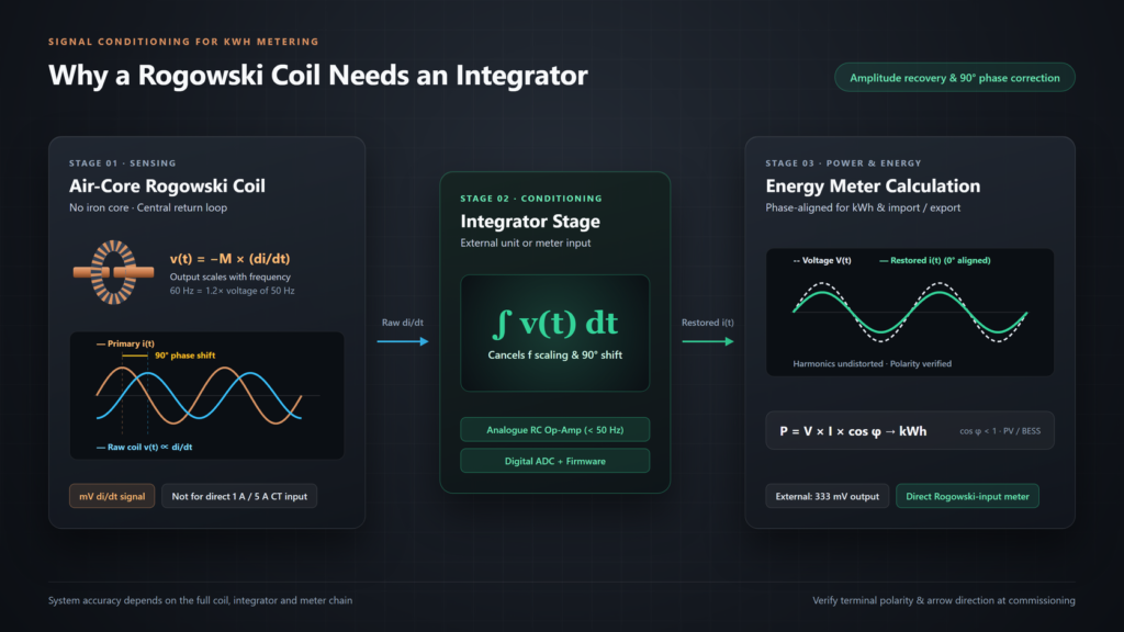
A Rogowski coil converts the changing magnetic field around a conductor into a di/dt voltage signal, and with no iron core it has nothing to saturate when fault currents spike.
Sensing Alternating Magnetic Flux
Under Ampère’s circuital law, the magnetic field integrated around a closed loop depends on the current enclosed, provided the turns are uniform and the ends close cleanly. The coil winds copper turns around a rigid or flexible non-magnetic former. A return conductor then runs back along the centre of the winding to reduce pickup from external fields, such as those from neighbouring busbars.
Without a steel core, the coil adds very little impedance to the primary conductor and its output stays linear over a wide current range without magnetic saturation. That absence of saturation is one of the points that separates Rogowski coils from current transformers in metering design.
Inducing a di/dt Voltage Signal
A changing current i(t) induces a terminal voltage described by Faraday’s law: v(t) = −M × (di/dt), where M is the mutual inductance set by turn density and the loop’s cross-sectional area. For sinusoidal AC, the derivative affects both amplitude and phase. The output amplitude scales with frequency, so at the same current a 60 Hz circuit produces 1.2 times the voltage of a 50 Hz circuit. Because the output is a millivolt signal rather than a current, a bare coil also cannot connect to a 1 A or 5 A CT input.
The raw voltage is also about 90 degrees out of phase with the primary current. With i(t) = I sin(ωt), the formula above gives v(t) = MωI sin(ωt − 90°), which is a 90-degree lag under that sign convention. Reversing the terminal polarity or the reference direction changes the sign, so whether the signal appears to lead or lag depends on how it is connected and defined.
Why a Rogowski Coil Needs an Integrator for Energy Metering
An energy meter calculates active power from voltage and current (P = V × I × cos φ) and accumulates kWh over time. An unintegrated di/dt signal meets neither need, so integration happens in an external converter module or in the meter’s own input stage.
Restoring True Current Amplitude
Integration (∫ v(t) dt) cancels the frequency multiplier introduced by differentiation and recovers a waveform proportional to the current i(t). Without it, harmonics from drives or EV chargers would appear larger than they are, in proportion to their order.
Analogue integrators use an op-amp RC feedback stage with a path that limits DC gain, so offset cannot saturate the amplifier. The lower cut-off frequency stays well below the 50 Hz fundamental. Digital meters instead digitise the raw di/dt voltage and integrate it in firmware, and the ADC and signal-processing architecture varies from design to design. Digital integration removes the drift of analogue integrator components, but the coil, ADC, voltage reference and signal conditioning can still drift, so the complete assembly still needs calibration.
Correcting the 90-Degree Phase Shift
Integration undoes the derivative, so the integrator output is again proportional to the current and the 90-degree difference disappears. What remains is polarity: the minus sign in the coil equation, or leads connected the other way round, can invert the waveform. Check the terminal polarity at installation and correct any remaining sign through polarity calibration in the meter.
Phase alignment decides kWh accuracy whenever loads run below unity power factor (cos φ), and it controls the import and export totals on PV or battery feeders. An external integrator typically provides a proportional voltage output, such as 333 mV. A 1 A or 5 A current output for a meter with conventional CT inputs needs an active converter designed and rated for that output. Do not treat a general Rogowski integrator as compatible with a 1 A or 5 A CT input unless its documentation states so. A Rogowski-input meter connects straight to the coil and saves the extra module in the panel.
Structural Types of Rogowski Coils
The sensing physics is the same in every air-core winding, but conductor shape, cabinet clearance and outage limits decide the former and the closure.
Rigid and Flexible Coils
Flexible coils wrap a bendable rope former around tight cable bundles and irregular busbars where a soland keep the required phase clearanceid body cannot clear the hardware around it. Rigid coils fix the turns on a non-magnetic ring, which holds the loop’s cross-section and winding pitch steady under vibration and heat cycling. One flexible loop length fits many conductor sizes, whereas a rigid coil is chosen for a specific aperture.
Split-Core and ClRigid Rogowski Coilsosed-Loop Designs
Split-core coils open at a mechanical joint, so they fit around cables or bolted busbars that are already installed without disconnecting the primary circuit. Closed-loop coils form an unbroken ring for Cable Length and Temperature Driftnew panel builds, where conductors pass through during assembly, and avoid the small discontinuity at a joint.
| Structural option | Former geometry | Retrofit without disconnection | Positional repeatability | Typical cabinet fit |
|---|---|---|---|---|
| Flexible split-core | Bendable rope with clasp | Yes | Needs ties or a centring clip | Dense cable looms and irregular busbars |
| Rigid split-core | Fixed ring with split joint | Yes | High geometric stability | Standardised retrofit feeders |
| Rigid closed-loop | Unbroken fixed ring | No, thread the conductor during the build | Most uniform winding, no joint | New switchboards and OEM assemblies |
What Affects Rogowski Coil Accuracy in Energy Metering
A percentage accuracy figure on the coil does not by itself establish Class 1 or Class 0.5 metering in the field. System accuracy depends on the whole coil, integrator and meter chain, together with conductor position, lead impedance and temperature.
Coil, Integrator and Meter Tolerances
IEC 61869-10 sets ratio-error and phase-error limits for low-power passive current transformers, including Rogowski coils without a built-in integrator; coils with an active integrator fall outside its scope. Those limits describe the coil alone, so add the integrator and meter tolerances when you work out system accuracy. At light load, a low-sensitivity coil can approach the noise floor of the measuring input unless external gain or multi-point offset, gain and phase calibration is applied.
Conductor Centring and External Fields
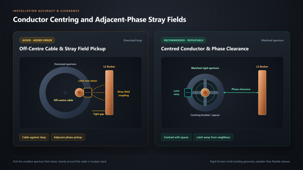
Real coils carry small winding tolerances and, on split designs, a slight discontinuity at the latch. A thin cable resting against the edge or clasp of an oversized loop therefore adds error, and flexible coils are generally more sensitive to conductor position than rigid ones.
Closely packed three-phase busbars can also couple stray fields into neighbouring coils. Centre each conductor with brackets or spacers, turn the clasps away from adjacent phases and keep the required phase clearance.
Cable Length and Temperature Drift
The shielded signal lead adds series resistance and capacitance that lower the high-frequency roll-off and change the gain into a finite input load. Keep the factory lead length intact rather than cutting or splicing it on site.
Temperature raises winding resistance while thermal expansion enlarges the former’s area. A rigid former usually balances those opposing effects more predictably than a flexible sleeve across a wide panel temperature range.
How to Select a Rogowski Coil for Energy Metering
Specify a Rogowski assembly in order: match the current range and meter input first, size the window to the conductors second, and confirm pairing and compliance documents before ordering.
Matching Current Range and Input
Size the rating around both the minimum normal load and the continuous peak current, because an oversized range pushes light loads towards the meter’s minimum current (Imin). Confirm the coil sensitivity (mV/kA or µV/A at 50 Hz in Europe) and whether your meter needs an external integrator or accepts a Rogowski coil directly. Check the rated sensitivity and coil-to-meter pairing in each datasheet before mixing parts across series.
Sizing the Coil Window
Measure the cable’s outer diameter or the full dimensions of a multi-bar busbar stack, then pick the smallest aperture that closes cleanly around the conductor. An oversized loop takes up cabinet space and makes centring less repeatable. Check door depth, bracket clearance and phase spacing against the panel drawings. For a split-core coil, also leave room to open it and seat the latch fully, because a latch that does not close properly adds error at the joint.
Verifying Pairing and Compliance
Before issuing a bill of materials, settle three points with your supplier:
- Confirm whether coils and meters ship calibrated together or need sensitivity and range programming on site.
- Specify the factory lead length in metres to avoid field splices, and match the arrow mark to the direction of power flow.
- Keep IEC and EN product standards separate from MID or national approvals for billing in the target EU, EEA or UK market.
Choose a YTL Rogowski-Input Meter and Coil
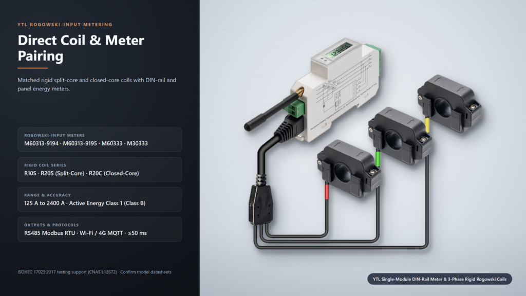
We supply meters that accept Rogowski coils directly and have also presented our own rigid coils, so you can work out the coil and meter pairing with one team.
Rogowski-Input Energy Meters
Our Rogowski-input energy meters include three DIN-rail models for compact European cabinets and a 96 mm panel meter for harmonic monitoring:
| YTL model | Format and wiring | Rogowski current range | Active energy | Communication and refresh | Typical use |
|---|---|---|---|---|---|
| M60313-9194 | 18 mm single-module DIN-rail (3P4W / 3P3W-V) | 200 A to 2400 A, split-core | Class 1 (Class B) | RS485 Modbus RTU, Wi-Fi and Bluetooth MQTT; ≤50 ms power-direction data refresh | Export-limit data for PV inverters or an EMS, BESS, EV charging |
| M60313-9195 | 18 mm single-module DIN-rail (3P4W / 3P3W-V) | 200 A to 2400 A, split-core | Class 1 (Class B) | RS485 Modbus RTU and 4G MQTT; ≤50 ms data refresh | Remote PV, storage and EV sites |
| M60333 | 54 mm three-module DIN-rail (3P4W) | Ib 20 A, Imax 600 A; up to 2400 A depending on the selected coil | Class 1 (Class B) | RS485 Modbus RTU and DL/T 645-2007; ≤75 ms RS485 communication refresh time; PT ratio up to 350:1; 4 tariffs | Factory, PV and BESS sub-metering |
| M30333 | 96 × 96 mm panel, up to 3 × 400/690 V | Ib 20 A, Imax 600 A | Class 1 (Class B) | RS485 Modbus RTU and DL/T 645-2007, plus Y-Bus for up to five temperature and humidity sensors; 2nd to 63rd harmonics; 6 tariffs; 4 DI / 2 DO; SOE records | Harmonic analysis in switchgear |
On the M60313 models the meter supplies power and direction data; the inverter or EMS performs any export control. Our test centre is accredited by CNAS to ISO/IEC 17025:2017 (registration no. CNAS L12672).
Rigid Rogowski Coils
We presented our rigid Rogowski coils at Enlit Europe 2026 in a standard and a high-accuracy series. Ask us for the coil datasheet, its test conditions and the recommended meter pairing before you specify one:
| Series | Construction | Rated currents |
|---|---|---|
| R10S (standard) | Rigid split-core | 125 A, 300 A, 500 A |
| R20S (high accuracy) | Rigid split-core | 200 A, 400 A, 600 A |
| R20C (high accuracy) | Rigid closed-core | 400 A, 600 A, 800 A, 1200 A, 2400 A |
Request a Matched Coil and Meter Proposal
Samples are welcome for evaluation, with availability and cost confirmed case by case. To get a matched coil and meter proposal, send us your project details:
- Voltage and wiring mode.
- Expected load range, from minimum normal load to continuous peak.
- Conductor or busbar dimensions.
- Protocol and data needs.
- Destination country and sample or batch quantities.
FAQ
Can a Rogowski Coil Measure DC?
No. Steady direct current has a di/dt of zero, so it induces no voltage in an air-core coil. The coil will not saturate under a DC offset on AC transients and can capture AC ripple on a DC bus, but it cannot meter steady DC energy. For EV DC chargers and batteries, specify a DC energy meter with a shunt or another DC-capable sensor.
What Happens If a Rogowski Coil Is Installed Backwards?
Mounting a coil with its arrow against the power flow, or swapping its leads at the meter, shifts the measured current by 180 degrees. On a load feeder, the meter then reports negative active power and logs energy in the export register instead of import. An export-limiting controller reading that meter may then act on false export data. Check the arrow orientation from source to load, the lead polarity and the phase pairing before enabling zero-export solar metering logic.
Can a Rogowski Coil Be Left Open-Circuited Under Load?
Generally yes. An open passive coil only presents its low output voltage, so it does not develop the hazardous voltage of an open iron-core CT secondary and needs no shorting terminals. The reading is another matter: depending on the meter’s input, an open lead may read zero, pick up interference, trigger a sensor alarm or return invalid data. Treat that channel as unreliable until it is reconnected.
Source
- IEC 61869-10:2017 Instrument transformers, Part 10: Additional requirements for low-power passive current transformers, International Electrotechnical Commission: the standard covering passive LPCTs, including Rogowski coils without a built-in integrator, and their ratio-error and phase-error limits.
